BUZZER INTERFACING WITH 8051
The Buzzer is an electronic device that converts the electronic signal into buzzing noise. Here we discuss working of buzzer when interfacing with AT89S52 microcontroller.
Synopsis

The Buzzer is an electronic device that converts the electronic signal into buzzing noise. The buzzer systems are widely used in school, colleges and TV programs. The team which presses the buzzer earliest is entitled to give the answer. At times it becomes very difficult to identify which team has pressed the button when two teams press the buzzer within a very small time gap. In such cases the decision can be biased due to human intervention. This buzzer disables the other inputs as soon as the first buzzer is pressed. It can be used for a maximum of eight teams.

Description

This quiz buzzer system has eight input pins corresponding to eight teams which show the number corresponding to the team which has pressed the button first. A buzzer is also sounded for a small duration to give an acoustic alarm. The microcontroller keeps scanning the input pins. As soon as any one of the inputs is pressed, the buzzer sounds for a small duration. Now even if any other input pin is pressed, there will be no effect on the system till the time the stop pin is pressed to reset the system. To interface a buzzer the standard transistor interfacing circuit is used. Note that if a different power supply is used for the buzzer, the 0V rails of each power supply must be connected to provide a common reference. If a battery is used as the power supply, it is worth remembering that piezo sounders draw much less current than buzzers. Buzzers also just have one ‘tone’, whereas a piezo sounder is able to create sounds of many different tones. To switch on buzzer - high 1 To switch off buzzer - low 1


Applications

• Alarm devices

• Timers

• Confirmation of user input (ex: mouse click or keystroke)

• Game shows

• Sporting events

• Household appliances

Proteus design for Buzzer interfacing with 8051


Orcad design for Buzzer interfacing with 8051


Buzzer interfacing with 8051

/*  Name     : main.c
 *  Purpose  : Source code for BUZZER Interfacing with AT89C52.
 *  Author   : Gemicates
 *  Date     : 2014-01-17
 *  Website  : www.gemicates.com
 *  Revision : None
 */
 
#include <REGX52.H>									// header file for AT89c52 series
#define input P1											
sbit Buzzer=P3^2;									// GPIO direction register declaration

void delay(unsigned int count);

void main()									        // main function
{
	input = 0xFF;									// Port 1 make as a output port
	while(1)
	{
		switch(input)								// Switch statement
		{
			case 0xFE:
				Buzzer = 0;
				delay(100);
				Buzzer = 1;
			  delay(100);
			break;
			
			case 0xFD:
				Buzzer = 0;
				delay(100);
				Buzzer = 1;
				delay(100);
			break;
			
			case 0xFB:
				Buzzer = 1;
				delay(100);
				Buzzer = 0;
				delay(100);
			break;
			
			case 0xF7:
				Buzzer = 1;
				delay(100);
				Buzzer = 0;
				delay(100);
			break;
			
			case 0xEF:
				Buzzer = 1;
				delay(100);
				Buzzer = 0;
				delay(100);
			break;
			
			case 0xDF:
				Buzzer = 1;
				delay(100);
				Buzzer = 0;
				delay(100);
			break;
			
			case 0xBF:
				Buzzer = 1;
				delay(100);
				Buzzer = 0;
				delay(100);
			break;
			
			case 0x7F:
				Buzzer = 1;
				delay(100);
				Buzzer = 0;
				delay(100);
			break;
			
		}
	}
}

void delay(unsigned int count)		                                                  //delay function declaration
{
	int i,j;
	for(i=0;i<count;i++)
	for(j=0;j<12750;j++);
}
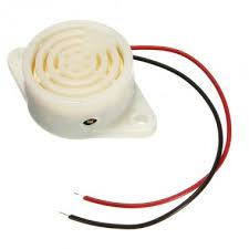
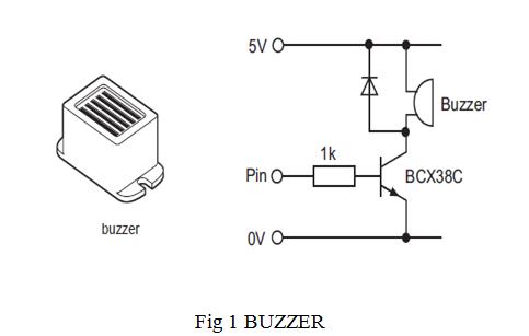
Interfacing of Buzzer with 8051

Error message here!

Show Error message here!


Forgot your password?

Error message here!

Send OTP

Error message here!

Show Error message here!


Lost your password? Please enter your email address. You will receive a password you Need.

Send Error message here!


Back to log-in

Close